
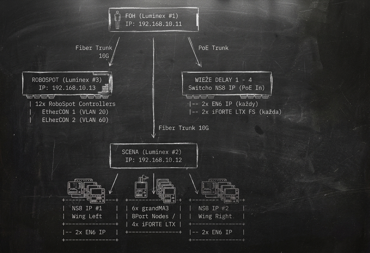
1. Założenia Ogólne i Lista Sprzętu
- Główne przeznaczenie: Transmisja protokołów oświetleniowych (MA-Net3 / sACN / Art-Net), transmisja multimediów, transmisja sygnału wideo z kamer HD, obsługa 12 stacji/kierownic RoboSpot oraz zarządzanie infrastrukturą.
- Switche Rdzeniowe (Core Switches): 3× Luminex GigaCore 30 (z obsługą PoE+/PoE++) zlokalizowane w węzłach FOH, Scena oraz Stanowisko RoboSpot. Połączenie magistralą światłowodową SFP+ Trunk / Link Redundancy (RLinkX) 10G.
- Switche Pomocnicze / Dystrybucyjne (Edge Switches): 6× Obsidian NETRON NS8 IP (IP65) na skrzydłach sceny (Wing Left, Wing Right) oraz wieżach opóźniających (Delay 1–4) zasilane przez PoE+ (IEEE 802.3at) bezpośrednio z FOH.
- Bramki Art-Net / sACN / DMX:
- Scena: 6× grandMA3 8Port Node podłączone do switcha Scena (Luminex GigaCore 30 #2).
- Wingi & Delay (2 bramki na węzeł): 12× Obsidian NETRON EN6 IP (po 2 sztuki podłączone do lokalnego switcha NS8 IP i zasilane przez PoE+).
- Lampy RoboSpot iFORTE® LTX FS:
- Wieże Delay (1–4): 8× Robe iFORTE® LTX FS (po 2 lampy na każdej z wież Delay 1–4 podłączone do switchy NS8 IP).
- Scena: 4× Robe iFORTE® LTX FS podłączone bezpośrednio do switcha Scena (Luminex GigaCore 30 #2).
- Podłączenie per lampa: 1× Port Ethernet Sterowanie (VLAN 20) + 1× Port Ethernet Kamera HD (VLAN 60).
- Kierownice / Kontrolery RoboSpot: 12× Kontroler Robe RoboSpot podłączone do switcha RoboSpot (Luminex #3).
- EtherCON 1: Sterowanie (sACN / Art-Net / MA-Net3 w VLAN 20).
- EtherCON 2: Odbiór wideo HD z przypisanej lampy (VLAN 60).
- System Sterowania FOH: 3× Konsolety grandMA3 (Full-size / Light – Main, Backup, Guest) + 6× grandMA3 Processing Unit L (PU L).
2. Adresacja IP i Podział na VLANy
A. Tabela Podsieci i VLANów
| VLAN ID | Nazwa VLAN | Zastosowanie / Protokoły | Zakres IP | Maska Sieci | Gateway / Serwer |
|---|---|---|---|---|---|
| VLAN 10 | Management | Zarządzanie switchami, RDM, GUI, Araneo, Web-Remote | 192.168.10.0/24 |
255.255.255.0 |
192.168.10.1 |
| VLAN 20 | Lighting Primary | MA-Net3 / sACN / Fixtures & RoboSpot Control | 192.168.0.0/24 |
255.255.255.0 |
Brak |
| VLAN 30 | Lighting Secondary | Art-Net / Secondary Lighting Control / Con 2 | 2.0.0.0/8 |
255.0.0.0 |
Brak |
| VLAN 40 | Multimedia Primary | Transmisja Multimediów (Main Stream) | 10.0.40.0/24 |
255.255.255.0 |
Brak |
| VLAN 50 | Multimedia Secondary | Transmisja Multimediów (Backup Stream) | 10.0.50.0/24 |
255.255.255.0 |
Brak |
| VLAN 60 | RoboSpot / Video | Sygnał wideo z kamer HD i odbiorniki wideo RoboSpot | 10.0.60.0/24 |
255.255.255.0 |
Brak |
B. Zestawienie Wykorzystanych i Wolnych Adresów IP
| VLAN ID | Podsieć | Wykorzystane Adresy IP | Zarezerwowana Rola / Przydział | Wolne / Dostępne Adresy IP |
|---|---|---|---|---|
| VLAN 10 | 192.168.10.0/24 |
192.168.10.1 192.168.10.11 – 192.168.10.13 192.168.10.21 – 192.168.10.22 192.168.10.31 – 192.168.10.34 |
Gateway / Router Switche Luminex Core Switche Edge Wing Switche Edge Delay |
192.168.10.2 – 192.168.10.10 192.168.10.14 – 192.168.10.20 192.168.10.23 – 192.168.10.30 192.168.10.35 – 192.168.10.254 |
| VLAN 20 | 192.168.0.0/24 |
192.168.0.11 – 192.168.0.13 192.168.0.21 – 192.168.0.26 192.168.0.51 – 192.168.0.56 192.168.0.61 – 192.168.0.64 192.168.0.71 – 192.168.0.78 192.168.0.101 – 192.168.0.112 192.168.0.121 – 192.168.0.128 192.168.0.141 – 192.168.0.144 |
grandMA3 Consoles grandMA3 PU L MA3 8Port Nodes NETRON EN6 (Wing) NETRON EN6 (Delay) RoboSpot Controllers (Ctrl) iFORTE Control (Delay) iFORTE Control (Stage) |
192.168.0.1 – 192.168.0.10 192.168.0.14 – 192.168.0.20 192.168.0.27 – 192.168.0.50 192.168.0.57 – 192.168.0.60 192.168.0.65 – 192.168.0.70 192.168.0.79 – 192.168.0.100 192.168.0.113 – 192.168.0.120 192.168.0.129 – 192.168.0.140 192.168.0.145 – 192.168.0.254 |
| VLAN 30 | 2.0.0.0/8 |
2.0.0.51 – 2.0.0.56 2.0.0.101 – 2.0.0.103 2.0.0.111 – 2.0.0.116 |
MA3 8Port Nodes (Con Alt) grandMA3 Consoles (Con 2) grandMA3 PU L (Con 2) |
2.0.0.1 – 2.0.0.50 2.0.0.57 – 2.0.0.100 2.0.0.104 – 2.0.0.110 2.0.0.117 – 2.0.0.254 |
| VLAN 40 | 10.0.40.0/24 |
Brak przypisań statycznych | Multimedia Primary Stream | 10.0.40.1 – 10.0.40.254 |
| VLAN 50 | 10.0.50.0/24 |
Brak przypisań statycznych | Multimedia Secondary Stream | 10.0.50.1 – 10.0.50.254 |
| VLAN 60 | 10.0.60.0/24 |
10.0.60.151 – 10.0.60.158 10.0.60.161 – 10.0.60.164 10.0.60.201 – 10.0.60.212 |
iFORTE Camera (Delay) iFORTE Camera (Stage) RoboSpot Controllers (Video) |
10.0.60.1 – 10.0.60.150 10.0.60.159 – 10.0.60.160 10.0.60.165 – 10.0.60.200 10.0.60.213 – 10.0.60.254 |
3. Statyczna Adresacja IP Urządzeń
A. Switche Rdzeniowe (Luminex GigaCore 30)
| Urządzenie | Lokalizacja | IP Zarządcze (VLAN 10) | Maska | Rola w Sieci |
|---|---|---|---|---|
| GigaCore 30 #1 | FOH | 192.168.10.11 |
255.255.255.0 | Main Core FOH / IGMP Querier / RSTP Root |
| GigaCore 30 #2 | Scena (Main Rack) | 192.168.10.12 |
255.255.255.0 | Stage Core / Secondary Root |
| GigaCore 30 #3 | Stanowisko RoboSpot | 192.168.10.13 |
255.255.255.0 | RoboSpot Distribution |
B. Switche Pomocnicze (Obsidian NETRON NS8 IP)
| Urządzenie | Lokalizacja | IP Zarządcze (VLAN 10) | Podłączenie Nadrzędne | Zasilanie NS8 IP |
|---|---|---|---|---|
| NS8 IP #1 | Wing Left | 192.168.10.21 |
Luminex #2 (Scena) Port 1 | 230V / PoE In |
| NS8 IP #2 | Wing Right | 192.168.10.22 |
Luminex #2 (Scena) Port 2 | 230V / PoE In |
| NS8 IP #3 | Delay 1 | 192.168.10.31 |
Luminex #1 (FOH) Port 1 | PoE+ z Luminex FOH |
| NS8 IP #4 | Delay 2 | 192.168.10.32 |
Luminex #1 (FOH) Port 2 | PoE+ z Luminex FOH |
| NS8 IP #5 | Delay 3 | 192.168.10.33 |
Luminex #1 (FOH) Port 3 | PoE+ z Luminex FOH |
| NS8 IP #6 | Delay 4 | 192.168.10.34 |
Luminex #1 (FOH) Port 4 | PoE+ z Luminex FOH |
C. System Sterowania FOH (grandMA3 Consoles & Processing Units)
| Urządzenie | Lokalizacja | IP Con 1 (VLAN 20) | IP Con 2 (VLAN 30) | Rola w Sesji |
|---|---|---|---|---|
| grandMA3 Console #1 | FOH Main | 192.168.0.11 |
2.0.0.101 |
Session Master (Primary) |
| grandMA3 Console #2 | FOH Backup | 192.168.0.12 |
2.0.0.102 |
Session Standby (Backup) |
| grandMA3 Console #3 | FOH / Pre-vis | 192.168.0.13 |
2.0.0.103 |
Session Member (Guest/Tech) |
| grandMA3 PU L #1 | FOH Rack | 192.168.0.21 |
2.0.0.111 |
Processing Expansion |
| grandMA3 PU L #2 | FOH Rack | 192.168.0.22 |
2.0.0.112 |
Processing Expansion |
| grandMA3 PU L #3 | FOH Rack | 192.168.0.23 |
2.0.0.113 |
Processing Expansion |
| grandMA3 PU L #4 | FOH Rack | 192.168.0.24 |
2.0.0.114 |
Processing Expansion |
| grandMA3 PU L #5 | FOH Rack | 192.168.0.25 |
2.0.0.115 |
Processing Expansion |
| grandMA3 PU L #6 | FOH Rack | 192.168.0.26 |
2.0.0.116 |
Processing Expansion |
D. Bramki DMX Sceniczne (grandMA3 8Port Nodes)
| Urządzenie | Lokalizacja | IP Con 1 Primary (VLAN 20) | IP Con Alternative (VLAN 30) | Uniwersa DMX | Wpięcie do Switcha |
|---|---|---|---|---|---|
| MA3 8Port Node #1 | Stage Rack / Truss A | 192.168.0.51 |
2.0.0.51 |
Univ 1 – 8 | Luminex #2 Port 3 (PoE+) |
| MA3 8Port Node #2 | Stage Rack / Truss B | 192.168.0.52 |
2.0.0.52 |
Univ 9 – 16 | Luminex #2 Port 4 (PoE+) |
| MA3 8Port Node #3 | Stage Floor / Center | 192.168.0.53 |
2.0.0.53 |
Univ 17 – 24 | Luminex #2 Port 5 (PoE+) |
| MA3 8Port Node #4 | Stage Floor / Upstage | 192.168.0.54 |
2.0.0.54 |
Univ 25 – 32 | Luminex #2 Port 6 (PoE+) |
| MA3 8Port Node #5 | Stage Side / Left | 192.168.0.55 |
2.0.0.55 |
Univ 33 – 40 | Luminex #2 Port 7 (PoE+) |
| MA3 8Port Node #6 | Stage Side / Right | 192.168.0.56 |
2.0.0.56 |
Univ 41 – 48 | Luminex #2 Port 8 (PoE+) |
E. Bramki Art-Net/sACN (Obsidian NETRON EN6 IP)
| Urządzenie | Lokalizacja | IP Primary (VLAN 20) | Uniwersa DMX | Zasilanie |
|---|---|---|---|---|
| NETRON EN6 IP #1 | Wing Left (Unit A) | 192.168.0.61 |
Univ 49 – 54 | PoE+ z NS8 IP #1 |
| NETRON EN6 IP #2 | Wing Left (Unit B) | 192.168.0.62 |
Univ 55 – 60 | PoE+ z NS8 IP #1 |
| NETRON EN6 IP #3 | Wing Right (Unit A) | 192.168.0.63 |
Univ 61 – 66 | PoE+ z NS8 IP #2 |
| NETRON EN6 IP #4 | Wing Right (Unit B) | 192.168.0.64 |
Univ 67 – 72 | PoE+ z NS8 IP #2 |
| NETRON EN6 IP #5 | Delay 1 (Unit A) | 192.168.0.71 |
Univ 73 – 78 | PoE+ z NS8 IP #3 |
| NETRON EN6 IP #6 | Delay 1 (Unit B) | 192.168.0.72 |
Univ 79 – 84 | PoE+ z NS8 IP #3 |
| NETRON EN6 IP #7 | Delay 2 (Unit A) | 192.168.0.73 |
Univ 85 – 90 | PoE+ z NS8 IP #4 |
| NETRON EN6 IP #8 | Delay 2 (Unit B) | 192.168.0.74 |
Univ 91 – 96 | PoE+ z NS8 IP #4 |
| NETRON EN6 IP #9 | Delay 3 (Unit A) | 192.168.0.75 |
Univ 97 – 102 | PoE+ z NS8 IP #5 |
| NETRON EN6 IP #10 | Delay 3 (Unit B) | 192.168.0.76 |
Univ 103 – 108 | PoE+ z NS8 IP #5 |
| NETRON EN6 IP #11 | Delay 4 (Unit A) | 192.168.0.77 |
Univ 109 – 114 | PoE+ z NS8 IP #6 |
| NETRON EN6 IP #12 | Delay 4 (Unit B) | 192.168.0.78 |
Univ 115 – 120 | PoE+ z NS8 IP #6 |
F. Lampy Robe iFORTE® LTX FS
| Urządzenie | Lokalizacja | IP Control (VLAN 20) | IP Camera Video (VLAN 60) | Przypisany Kontroler RoboSpot |
|---|---|---|---|---|
| iFORTE LTX FS #1 | Delay 1 | 192.168.0.121 |
10.0.60.151 |
RoboSpot Controller #1 |
| iFORTE LTX FS #2 | Delay 1 | 192.168.0.122 |
10.0.60.152 |
RoboSpot Controller #2 |
| iFORTE LTX FS #3 | Delay 2 | 192.168.0.123 |
10.0.60.153 |
RoboSpot Controller #3 |
| iFORTE LTX FS #4 | Delay 2 | 192.168.0.124 |
10.0.60.154 |
RoboSpot Controller #4 |
| iFORTE LTX FS #5 | Delay 3 | 192.168.0.125 |
10.0.60.155 |
RoboSpot Controller #5 |
| iFORTE LTX FS #6 | Delay 3 | 192.168.0.126 |
10.0.60.156 |
RoboSpot Controller #6 |
| iFORTE LTX FS #7 | Delay 4 | 192.168.0.127 |
10.0.60.157 |
RoboSpot Controller #7 |
| iFORTE LTX FS #8 | Delay 4 | 192.168.0.128 |
10.0.60.158 |
RoboSpot Controller #8 |
| iFORTE LTX FS #9 | Stage / Truss Front | 192.168.0.141 |
10.0.60.161 |
RoboSpot Controller #9 |
| iFORTE LTX FS #10 | Stage / Truss Front | 192.168.0.142 |
10.0.60.162 |
RoboSpot Controller #10 |
| iFORTE LTX FS #11 | Stage / Truss Mid | 192.168.0.143 |
10.0.60.163 |
RoboSpot Controller #11 |
| iFORTE LTX FS #12 | Stage / Truss Back | 192.168.0.144 |
10.0.60.164 |
RoboSpot Controller #12 |
G. Kierownice / Kontrolery RoboSpot
| Urządzenie | IP EtherCON 1 Control (VLAN 20) | IP EtherCON 2 Video (VLAN 60) | Obsługiwana Lampa | Wpięcie do Switcha |
|---|---|---|---|---|
| RoboSpot Controller #1 | 192.168.0.101 |
10.0.60.201 |
iFORTE LTX FS #1 (Delay 1) | Luminex #3 (Porty 1 & 13) |
| RoboSpot Controller #2 | 192.168.0.102 |
10.0.60.202 |
iFORTE LTX FS #2 (Delay 1) | Luminex #3 (Porty 2 & 14) |
| RoboSpot Controller #3 | 192.168.0.103 |
10.0.60.203 |
iFORTE LTX FS #3 (Delay 2) | Luminex #3 (Porty 3 & 15) |
| RoboSpot Controller #4 | 192.168.0.104 |
10.0.60.204 |
iFORTE LTX FS #4 (Delay 2) | Luminex #3 (Porty 4 & 16) |
| RoboSpot Controller #5 | 192.168.0.105 |
10.0.60.205 |
iFORTE LTX FS #5 (Delay 3) | Luminex #3 (Porty 5 & 17) |
| RoboSpot Controller #6 | 192.168.0.106 |
10.0.60.206 |
iFORTE LTX FS #6 (Delay 3) | Luminex #3 (Porty 6 & 18) |
| RoboSpot Controller #7 | 192.168.0.107 |
10.0.60.207 |
iFORTE LTX FS #7 (Delay 4) | Luminex #3 (Porty 7 & 19) |
| RoboSpot Controller #8 | 192.168.0.108 |
10.0.60.208 |
iFORTE LTX FS #8 (Delay 4) | Luminex #3 (Porty 8 & 20) |
| RoboSpot Controller #9 | 192.168.0.109 |
10.0.60.209 |
iFORTE LTX FS #9 (Stage) | Luminex #3 (Porty 9 & 21) |
| RoboSpot Controller #10 | 192.168.0.110 |
10.0.60.210 |
iFORTE LTX FS #10 (Stage) | Luminex #3 (Porty 10 & 22) |
| RoboSpot Controller #11 | 192.168.0.111 |
10.0.60.211 |
iFORTE LTX FS #11 (Stage) | Luminex #3 (Porty 11 & 23) |
| RoboSpot Controller #12 | 192.168.0.112 |
10.0.60.212 |
iFORTE LTX FS #12 (Stage) | Luminex #3 (Porty 12 & 24) |
4. Topologia Połączeń Fizycznych
                               ===========================
                               |    FOH (Luminex #1)     |
                               |    IP: 192.168.10.11    |
                               ===========================
                                 /          |          \
                     Fiber Trunk /          |           \ PoE Trunk
                            10G /           |            \
                               v            |             v
     ===========================            |        ===========================
     |  ROBOSPOT (Luminex #3)  |            |        |   WIEŻE DELAY 1 – 4     |
     |    IP: 192.168.10.13    |            |        | Switche NS8 IP (PoE In) |
     ===========================            |        ===========================
       | 12x RoboSpot Controllers           |          |-- 2x EN6 IP (każdy)
       |   EtherCON 1 (VLAN 20)             |          |-- 2x iFORTE LTX FS (każda)
       |   EtherCON 2 (VLAN 60)             |
                                            | Fiber Trunk 10G
                                            v
                               ===========================
                               |   SCENA (Luminex #2)    |
                               |    IP: 192.168.10.12    |
                               ===========================
                                 /          |          \
                                /           |           \
                               v            v            v
                 +---------------+  +---------------+  +---------------+
                 |  NS8 IP #1    |  | 6x grandMA3   |  |  NS8 IP #2    |
                 |  Wing Left    |  | 8Port Nodes   |  |  Wing Right   |
                 +---------------+  | 4x iFORTE LTX |  +---------------+
                 |-- 2x EN6 IP   |  +---------------+  |-- 2x EN6 IP   |
                 +---------------+                     +---------------+
5. Szczegółowa Mapacja Portów Switchy
A. Switch Luminex FOH (GigaCore 30 #1)
| Port RJ45/SFP+ | VLAN ID | Przypisana Rola / Urządzenie | Zasilanie PoE | Uwagi / Protokół |
|---|---|---|---|---|
| Port 1 | Trunk (10,20,60) | NS8 IP #3 (Delay 1) | PoE+ Enabled | DMX, Mgmt, RoboSpot Cam Video |
| Port 2 | Trunk (10,20,60) | NS8 IP #4 (Delay 2) | PoE+ Enabled | DMX, Mgmt, RoboSpot Cam Video |
| Port 3 | Trunk (10,20,60) | NS8 IP #5 (Delay 3) | PoE+ Enabled | DMX, Mgmt, RoboSpot Cam Video |
| Port 4 | Trunk (10,20,60) | NS8 IP #6 (Delay 4) | PoE+ Enabled | DMX, Mgmt, RoboSpot Cam Video |
| Port 5 | Trunk (20,30) | grandMA3 Console #1 (Main) | Disabled | Port Con 1 (192.168.0.11) / Con 2 (2.0.0.101) |
| Port 6 | Trunk (20,30) | grandMA3 Console #2 (Backup) | Disabled | Port Con 1 (192.168.0.12) / Con 2 (2.0.0.102) |
| Port 7 | Trunk (20,30) | grandMA3 Console #3 (Guest) | Disabled | Port Con 1 (192.168.0.13) / Con 2 (2.0.0.103) |
| Port 8–13 | Trunk (20,30) | grandMA3 PU L #1 do #6 | Disabled | Porty Con 1 (VLAN 20) / Con 2 (VLAN 30) |
| Port 14–15 | VLAN 40 | Multimedia Primary | Disabled | Multimedia Stream Main |
| Port 16–17 | VLAN 50 | Multimedia Secondary | Disabled | Multimedia Stream Backup |
| Port 18–20 | VLAN 10 | Laptop Realizatora / Access Point | PoE+ (dla AP) | Araneo, MA Web-Remote |
| SFP+ 1-2 | Trunk (All) | Światłowód Core: Scena (Luminex #2) | N/A | Link Redundancy (RLinkX) 10G |
| SFP+ 3-4 | Trunk (All) | Światłowód Core: RoboSpot (Luminex #3) | N/A | Link Redundancy (RLinkX) 10G |
B. Switch Luminex Scena (GigaCore 30 #2)
| Port RJ45/SFP+ | VLAN ID | Przypisana Rola / Urządzenie | Zasilanie PoE | Uwagi / Protokół |
|---|---|---|---|---|
| Port 1 | Trunk (10,20) | NS8 IP #1 (Wing Left) | Disabled | Uplink do switcha brzegowego Wing Left |
| Port 2 | Trunk (10,20) | NS8 IP #2 (Wing Right) | Disabled | Uplink do switcha brzegowego Wing Right |
| Port 3–8 | Trunk (20,30) | 6× grandMA3 8Port Node (#1–#6) | PoE+ Enabled | Con 1 Primary (VLAN 20) / Con Alt (VLAN 30) |
| Port 9–12 | VLAN 20 | 4× iFORTE LTX FS (#9–#12) Control | Disabled | Sterowanie sACN / Art-Net / MA-Net3 |
| Port 13–16 | VLAN 60 | 4× iFORTE LTX FS (#9–#12) Camera | Disabled | Transmisja obrazu HD z kamer RoboSpot |
| Port 17–18 | VLAN 40 | Multimedia Primary | Disabled | Multimedia Stream Main |
| Port 19–20 | VLAN 50 | Multimedia Secondary | Disabled | Multimedia Stream Backup |
| Port 21–24 | VLAN 10 | Dostęp serwisowy / Araneo / RDM | Disabled | Management |
| SFP+ 1-2 | Trunk (All) | Światłowód Core: FOH (Luminex #1) | N/A | Link Redundancy (RLinkX) 10G |
| SFP+ 3-4 | Trunk (All) | Światłowód Core: RoboSpot (Luminex #3) | N/A | Link Redundancy (RLinkX) 10G |
C. Switch Luminex RoboSpot (GigaCore 30 #3)
| Port RJ45/SFP+ | VLAN ID | Przypisana Rola / Urządzenie | Zasilanie PoE | Uwagi / Protokół |
|---|---|---|---|---|
| Port 1–12 | VLAN 20 | 12× RoboSpot Controller (EtherCON 1) | Disabled | Sterowanie / sACN / Art-Net / MA-Net3 |
| Port 13–24 | VLAN 60 | 12× RoboSpot Controller (EtherCON 2) | Disabled | Odbiór sygnału wideo HD z kamer lamp |
| SFP+ 1-2 | Trunk (All) | Światłowód Core: FOH (Luminex #1) | N/A | Link Redundancy (RLinkX) 10G |
| SFP+ 3-4 | Trunk (All) | Światłowód Core: Scena (Luminex #2) | N/A | Link Redundancy (RLinkX) 10G |
D. Switche Brzegowe Delay (NETRON NS8 IP #3 – #6)
| Port RJ45 | VLAN ID | Przypisana Rola / Urządzenie | Zasilanie PoE | Uwagi |
|---|---|---|---|---|
| Port 1 | VLAN 20 | NETRON EN6 IP (Unit A) | PoE+ Enabled | DMX Gateways A (np. Delay 1 Univ 73–78) |
| Port 2 | VLAN 20 | NETRON EN6 IP (Unit B) | PoE+ Enabled | DMX Gateways B (np. Delay 1 Univ 79–84) |
| Port 3 | VLAN 20 | iFORTE LTX FS #1 (Control) | Disabled | Sterowanie sACN / Art-Net / MA-Net3 |
| Port 4 | VLAN 20 | iFORTE LTX FS #2 (Control) | Disabled | Sterowanie sACN / Art-Net / MA-Net3 |
| Port 5 | VLAN 60 | iFORTE LTX FS #1 (Camera Video) | Disabled | Transmisja obrazu HD z kamery śledzącej |
| Port 6 | VLAN 60 | iFORTE LTX FS #2 (Camera Video) | Disabled | Transmisja obrazu HD z kamery śledzącej |
| Port 7 | VLAN 10 | Dostęp Serwisowy / Laptop | Disabled | Management |
| Port 8 (Uplink) | Trunk (10,20,60) | Uplink do Luminex FOH (#1) | PoE In | Zasilanie switcha NS8 IP bezpośrednio z FOH |
6. Zasilanie PoE i Ustawienia Konfiguracyjne
Specyfikacja Budżetu Mocy PoE
- Switche Dystrybucyjne NS8 IP na Delayach: Zasilane bezpośrednio poprzez kabel ethernetowy z portów 1–4 switcha Luminex FOH (GigaCore 30 #1) w standardzie PoE+ (IEEE 802.3at).
- Bramki grandMA3 8Port Node: 6× bramek na scenie zasilanych jest z portów 3–8 switcha Luminex Scena w standardzie PoE+ (IEEE 802.3at) (~15W per urządzenie, łącznie ~90W).
- Bramki NETRON EN6 IP: 12× bramek (po 2 sztuki na Wing L/R oraz Delay 1–4) zasilanych z portów PoE+ lokalnych switchy NS8 IP (~10W per urządzenie).
- Robe iFORTE® LTX FS oraz Kontrolery RoboSpot: Zasilane lokalnie 230V AC z rozdzielni prądowych.
Lista Kontrolna Konfiguracji (Checklist)
- PoE Management: Włączyć PoE+ (802.3at) na Portach 1–4 w Luminex FOH, Portach 3–8 w Luminex Scena oraz Portach 1–2 na switchach NS8 IP.
- IGMP Snooping & Querier:
- Włączyć IGMP Snooping na VLAN 20 (Lighting Primary), VLAN 30 (Lighting Secondary), VLAN 40/50 (Multimedia) oraz VLAN 60 (RoboSpot Video).
- Włączyć IGMP Querier na głównym switchu Luminex FOH (#1) oraz pasywny (Backup Querier) na Luminex Scena (#2).
- Quality of Service (QoS): Zastosować predefiniowany profil Multimedia / MA-Net3 / sACN / Video Stream w panelu Luminex Araneo.
Dodaj komentarz